Choosing Device Current Waveform Analyzers is not simply a matter of selecting the highest bandwidth or fastest sampling rate. The right instrument must reveal what the device actually experiences during startup, switching, sleep, and fault conditions. A clean waveform on screen can still hide probe loading, ground-loop noise, or a missed transient.
Lord Kelvin, a foundational expert in electrical measurement, stated, “To measure is to know.” That principle remains practical today. Engineers should examine current range, bandwidth, sample memory, trigger stability, isolation, and measurement uncertainty. A microamp sleep current may require a different setup from a motor driver producing sharp ampere-level pulses. The same analyzer may not handle both accurately.
Details matter. A short, wide connection can reduce unwanted inductance. A properly rated shunt can preserve waveform shape. Differential probes can prevent dangerous ground references and confusing artifacts. Yet specifications alone do not guarantee useful results. Some instruments advertise impressive resolution, but their noise floor becomes visible during a quiet 2 mA interval.
This guide explains how to compare Device Current Waveform Analyzers for real laboratory conditions. It considers sensor choice, dynamic range, trigger behavior, software analysis, calibration, and future testing needs. No analyzer is perfect. A costly model can still produce questionable data when the setup is careless. That is an uncomfortable point, but it deserves attention. The best choice balances accuracy, usability, safety, and the waveform details your device truly requires.
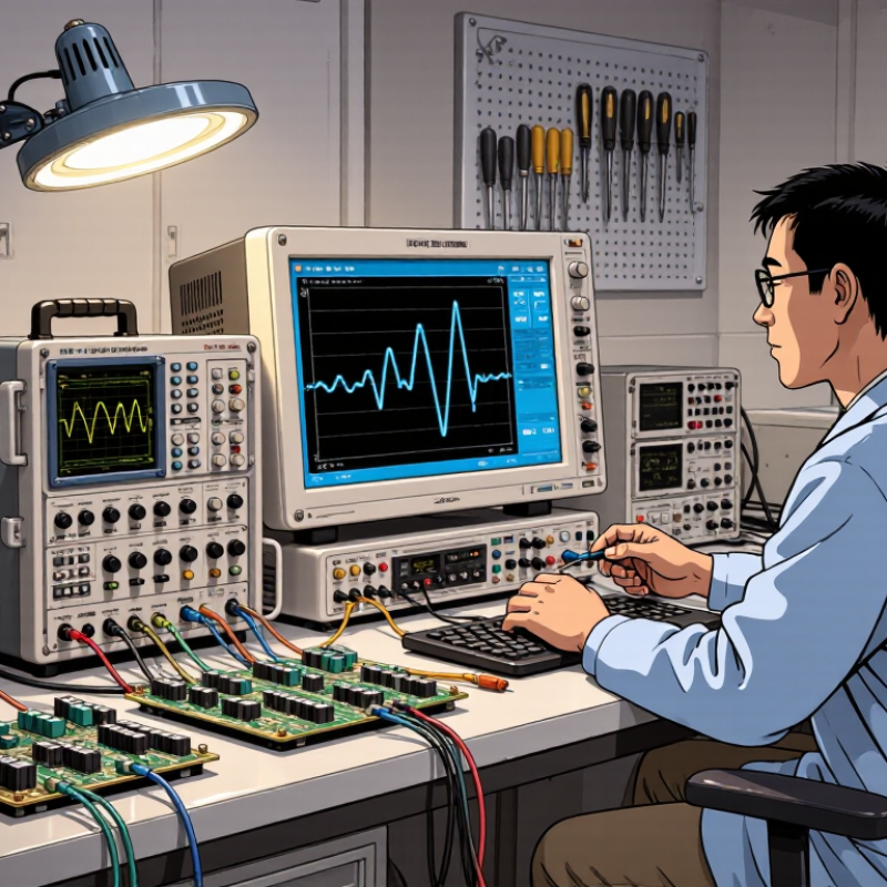
Choosing a device current waveform analyzer begins with a measurement goal, not a feature list. In lab practice, engineers often confuse average consumption with dynamic behavior. Define whether you need standby current, startup inrush, sleep-to-active transitions, or short wireless bursts. Each event demands different bandwidth, sampling speed, trigger control, and memory depth.
The device current requirement must be written numerically. Record the expected minimum and peak current, voltage range, pulse duration, repetition rate, and allowable measurement burden. IEC 62301 provides guidance for standby-power measurements, while the IEA Electricity 2024 report estimates that data centers consumed about 460 TWh globally in 2022. It projects consumption could exceed 1,000 TWh by 2026. These figures underline why small errors during low-power states still matter.
For a sensor drawing microamps, prioritize low noise and burden voltage. For a processor with millisecond load steps, prioritize fast sampling, wide bandwidth, and reliable triggering. A suitable analyzer should capture the complete waveform, not only a calculated average.
Check input isolation and protection before connecting an unfamiliar prototype. This is often overlooked. Also compare readings against a calibrated reference meter and repeat tests across temperature and battery voltage. Perfect repeatability is unlikely; cables, probes, and firmware timing can alter the result. A practical choice may need fewer headline specifications and better evidence from real operating conditions.
How to Choose Device Current Waveform Analyzers?
When choosing a device current waveform analyzer, start with waveform accuracy. A clean display does not always mean a trustworthy measurement. Check vertical resolution, noise level, offset accuracy, and calibration stability. During bench testing, compare readings against a known reference current. Small errors become visible when the load changes quickly. Probe placement also matters. Long ground leads can add ringing that does not exist in the circuit.
Bandwidth must match the fastest event you need to observe. A slow converter may work well with moderate bandwidth, while switching edges require more headroom. Insufficient bandwidth rounds peaks and hides overshoot. Excessive bandwidth can expose unwanted noise. That can confuse interpretation. Sampling performance is equally important. Select a sampling rate high enough to capture narrow pulses without aliasing. Review memory depth too, especially when recording long startup sequences. A high sampling rate with shallow memory may capture only a few microseconds.
Tips: Test the analyzer with a repeatable signal before measuring the target device. Compare time-base accuracy, trigger stability, and waveform amplitude. I once trusted an attractive waveform and missed a brief current spike. The setup looked correct, but the trigger level was poorly chosen. Recheck cables, probe compensation, and thermal drift after several minutes. Measurements are never perfectly neutral. Their quality depends on both the instrument and the person using it.
| Analyzer Class | Typical Analog Bandwidth | Maximum Sample Rate | Vertical Resolution | Typical Amplitude Accuracy | Record Length | Best-Suited Applications |
|---|---|---|---|---|---|---|
| Basic Bench Analyzer | 20–100 MHz | 100 MS/s–1 GS/s | 8-bit | Approximately ±2% to ±4% of reading | 1–10 Mpoints | Low-frequency current behavior, switching checks, and general troubleshooting |
| General-Purpose Digital Analyzer | 100–350 MHz | 1–5 GS/s | 8-bit or 10-bit | Approximately ±1.5% to ±3% of reading | 10–50 Mpoints | Power-converter development, inrush current, PWM edges, and transient analysis |
| High-Speed Waveform Analyzer | 350 MHz–1 GHz | 5–20 GS/s | 8-bit or 10-bit | Approximately ±1% to ±2% of reading | 50–500 Mpoints | Fast switching devices, gate-loop behavior, ringing, overshoot, and EMI-related events |
| Precision Current Measurement System | DC–100 MHz, depending on the current sensor | 100 MS/s–2 GS/s | 12-bit to 16-bit | Approximately ±0.5% to ±1.5% of reading | 1–100 Mpoints | Low-level current, standby power, control-loop measurements, and accurate RMS analysis |
| Long-Memory Transient Analyzer | 50–500 MHz | 500 MS/s–5 GS/s | 8-bit to 12-bit | Approximately ±1% to ±3% of reading | 100 Mpoints–1 Gpoint | Intermittent faults, load transitions, battery systems, startup sequences, and long-duration captures |
Choosing a current waveform analyzer starts with input compatibility, not display resolution. Check voltage range, connector type, bandwidth, sampling rate, and channel isolation. A sensor may produce millivolt signals, while another outputs several volts. The analyzer must accept that signal without clipping or burying small changes in noise.
Safety requires practical checking. Confirm the input’s isolation rating, measurement category, overvoltage protection, and grounding method. Keep probe leads short and secured near the test device. A loose lead can create ringing that looks like a real switching event. Never assume a high-priced instrument is automatically safe. Review its manual and applicable safety standards.
Current-sensing methods shape the waveform you see. Shunt resistors offer excellent bandwidth, but they add insertion loss and require careful thermal design. Current transformers provide isolation for alternating current, yet they cannot reproduce steady direct current. Hall sensors measure both directions, although offset drift can weaken low-current accuracy. Rogowski coils handle fast, large pulses, but they need integration and careful positioning.
I once trusted a clean waveform too quickly. Later, probe placement revealed unexpected ground-loop noise. That mistake changed my test routine. Measure a known reference, compare sensor outputs, and record the setup with photographs. Also inspect crest factor and peak limits, not only RMS accuracy. The best choice fits the device, sensing method, safety boundary, and uncertainty of the measurement.
Assess software features before comparing sampling rates. A fast instrument still fails when software hides brief current spikes. In laboratory testing, I look for adjustable triggers, segmented memory, pre-trigger capture, and synchronized voltage channels. These features reveal startup surges, switching noise, and control-loop instability.
The International Energy Agency reported nearly 14 million electric car sales in 2023.
That growth increases demand for precise power-electronics validation. Small timing errors matter.
Data analysis should turn raw waveforms into repeatable evidence. Choose software that supports automated measurements, harmonic analysis, statistical trends, and exportable reports. It should preserve sampling settings, probe information, timestamps, and calibration status. Otherwise, a clean graph may be difficult to defend months later.
The IEEE 1588 precision-time protocol can support synchronized measurements across distributed test equipment. However, synchronization alone does not guarantee useful data.
Trigger design still needs practical review.
Integration is equally important. Check for documented APIs, remote commands, REST access, and industrial protocols such as OPC UA or MQTT. A device should connect with test automation, databases, and digital-twin platforms without fragile scripts.
The 2024 Cost of a Data Breach Report placed the average breach cost at 4.88 million dollars, reinforcing the need for access control and audit logs.
Security is often overlooked. I have also seen teams collect impressive datasets that nobody can interpret. That is a design failure, not merely a training problem.
Choose transparent software, readable file formats, and analysis tools that engineers can verify.
Choosing a device current waveform analyzer starts with the budget, but price alone can mislead. A lower-cost unit may fit simple power tests, while advanced devices need wider bandwidth, faster sampling, and a lower noise floor. Check the smallest current pulse you must capture. Also check the highest continuous current.
Usability affects every measurement. A clear display, responsive controls, and sensible triggering can save hours at the bench. Look for isolated inputs, safe probe connections, and software that exports raw data. In practical testing, I prefer analyzers that show overshoot, ringing, and settling time without complicated menus.
Small details matter. Poor cables can distort a clean waveform. I once blamed an analyzer for noise that came from an unsuitable probe. That mistake was expensive and useful.
Future needs deserve equal attention. Consider planned products, higher switching speeds, automated testing, and remote data access. Choose enough memory and bandwidth for upcoming work, but avoid paying for specifications you cannot use. Confirm calibration support, documentation quality, and repair options before purchase. A familiar interface may be more valuable than an impressive specification sheet. Still, convenience should not replace verification. Test the analyzer with a known signal, compare repeated captures, and record its limits under real operating conditions.
Check waveform accuracy, noise level, vertical resolution, offset accuracy, and calibration stability. Compare measurements with a known reference current. A clean display can still mislead.
Long ground leads can create ringing that is absent from the circuit. Keep connections short and position the probe carefully. The setup matters.
Match bandwidth to the fastest event you need to observe. Insufficient bandwidth rounds peaks and hides overshoot. Excessive bandwidth may reveal confusing noise.
Use a sampling rate high enough to capture narrow pulses without aliasing. Check memory depth for long startup recordings. Fast sampling needs enough memory.
Poor trigger levels can hide brief current spikes. Use adjustable triggers and pre-trigger capture when possible. I once trusted the picture too quickly.
Useful software provides automated measurements, harmonic analysis, statistical trends, and exportable reports. It should preserve probe details, timestamps, settings, and calibration status. Otherwise, later verification becomes difficult.
Look for documented APIs, remote commands, and compatible industrial communication methods. The analyzer should connect with automation systems, databases, and simulation platforms. Fragile scripts create avoidable problems.
Use access controls, audit logs, and readable data formats. Protect stored measurements and remote connections. Security is easy to overlook.
Choosing the right Device Current Waveform Analyzers begins with clearly defining your measurement goals, including the expected current range, waveform types, operating conditions, and required test accuracy. Compare each analyzer’s waveform accuracy, bandwidth, sampling rate, resolution, and triggering performance to ensure it can capture both fast transients and subtle current changes. It is also important to evaluate input compatibility, electrical safety, isolation requirements, and the current-sensing method, such as direct measurement or external sensors.
Beyond hardware performance, consider software functions for real-time monitoring, waveform visualization, automated measurements, data recording, and report generation. Compatibility with existing instruments, control systems, and data platforms can improve overall testing efficiency. Finally, balance purchase cost with usability, maintenance needs, training requirements, and future expansion. A well-selected analyzer should meet current testing demands while providing enough flexibility to support new devices, higher performance requirements, and evolving measurement applications.